
Greenhouse Gas Measurement Lab
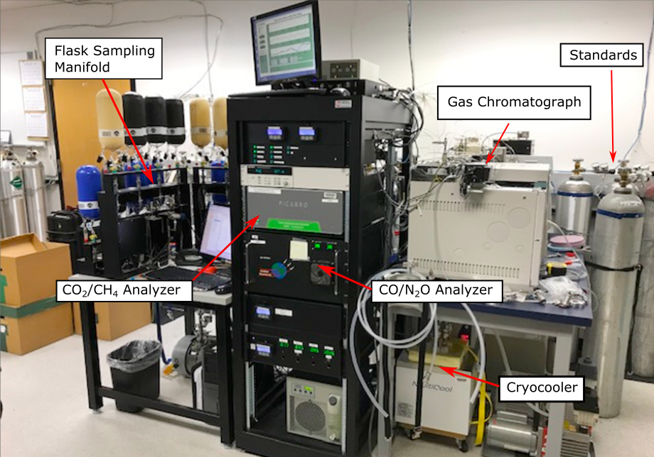
All six gases are measured in one single system. Air from a sample is directed through a series of tubes and to the different analyzers where each gas is measured. Air from a standard tank is analyzed between each sample to calibrate the system.
Connecting the Samples
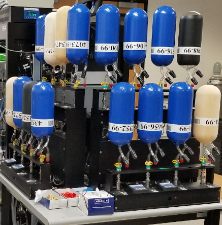
The sample manifold is set up to handle the different types of samples and standards that come into the lab: flasks, automated multi-flask packages (twelve-packs), and standard cylinders. They all get measured in the same way, but the connections to get the air out of the container and into the measurement instruments is slightly different for each type.
- The sampling manifold is a circular device that allows eight individual sample flasks to be connected at once. A special vacuum grease is used to make a seal so that no room air can get back in during the measurement process.
- Twelve-packs are connected at a slightly different place on the system, and instead of using grease, they are connected with a “quick connect” coupling, a kind of connection that is easily connected or disconnected but seals very well and seldom leaks.
- Standards are connected directly to the second valve (the sample select valve) also using quick connects.
Evacuation
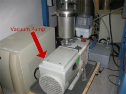 Before the gas can begin its journey, all of the room air must be evacuated from the tube between where the flask is connected and the stream selection valve. This is done using a vacuum pump to suck all of the air out of the tubing and manifold. It’s not possible to perfectly remove every last bit of air, but we come close, leaving only 1/10000th of the original air. Occasionally, the system springs a leak, and like the opposite of a leaky bike tire, as fast as the vacuum pump sucks air out, more leaks back in. When this happens, technicians have to find and repair the leak.
Computer Control
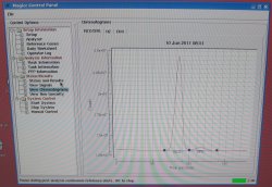
The entire measurement process is controlled by software that is programmed to run the checks prior to analysis, communicate with the analyzers to give commands and record measurements, and determine which sample or standard is flowing through the system. The technician’s job is to load the samples and standards and tell the computer which samples are in each location so that the measurements may be assigned to the correct sample. The technicians and scientists at CCGG monitor the output to make sure that everything is operating smoothly.
Gases on the Go
Once the eight samples or twelve-packs have been connected to the “sample inlet lines,” (tubes that run to the first stream selection valve) and the computer has determined that the system is leak-tight, the computer determines that it is time to run the first sample. A transfer pump moves the gas from one of the samples through the stream selection valve and into the system. All of the samples and standards measured come in to the sample select valve. The sample select valve acts like a traffic cop directing the traffic into a one-way exit after a major sporting event. Many cars from different locations meet at the cop, who lets only one car through at a time in one exit direction. Similar to the traffic cop, the computer and the valve together, tell which gas can exit and head forward towards the mass flow controller.
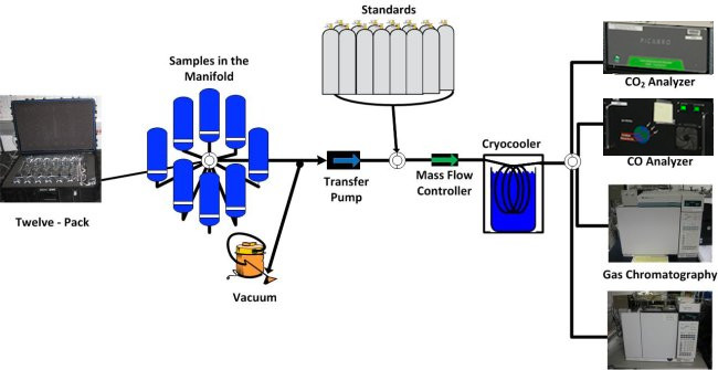
The mass flow controller and the analyzer select valve work together to determine the volume or how much of the gas will be measured by which machine. When the analyzer select valve is opened to a particular analyzer, the mass flow controller lets a predetermined amount of gas through, depending on which gas will be analyzed.
Drying the Air Sample
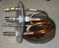
Water vapor can interfere with the measurements, so we must be certain that it is completely dry before the air enters the analyzers. The gas passes through a cryocooler. A cryocooler is essentially a very cold freezer! A temperature of -80 ˚C (-112 ˚F!) is used to freeze all of the water vapor from the air and on to the inside walls of the tube.
See the ice on the outside of the tube? This is the ice from the air in the room, but you can imagine that the ice builds up on the inside too. Eventually, enough water freezes into the water trap that it can become completely blocked, so the water trap is removed and dried every day.
After it is completely dry, the air sample finally reaches the analyzer select valve, which acts like a bit like a traffic light on a one-way street. You can turn many directions depending on which way the light tells you to go, but you can not go back to where you came from. This just means that the system select valve determines which analyzer the gas will go to. The system select valve switches between the four different analyzers so that some of the air from each sample goes to each analyzer.
Next: Gas Analyzers Previous