
Aircraft Measurements
The CCGG group’s aircraft program has been dedicated to collecting air samples in vertical profiles even higher in the atmosphere than can be reached by the Tall Tower network. The program's mission is to capture seasonal and inter-annual (between years, or from one year to the next) changes in trace gas concentrations throughout the boundary layer and free troposphere (up to 8,000 m/26,000 ft). At present, most aircraft flights collect 12 air samples at different altitudes up to 13,279 m/43,555 ft . These samples are stored in glass flasks for later analysis at the Boulder Central Facility.
Read more about the aircraft sampling sites...
Data collected by the aircraft program provide a view of how the large-scale horizontal and vertical distribution of the measured trace gases change throughout a given year over the continent. This three-dimensional picture of how trace gas concentrations change throughout the year has provided a means to estimate the contribution of CO2 and other long-lived trace gases from the North American continent. Since we are sampling air way up into the troposphere, the air is influenced by a much larger area on the surface (called a "footprint") compared to surface and tall tower sampling. Aircraft sampling allows us to see where CO2 and other greenhouse gases go after being emitted at the surface because the gases emitted at the surface mix their way up into the free troposphere over time and are blown wherever the winds are moving. Data from aircraft sampling are used to verify computer models, like CarbonTracker, that model CO2 concentrations across the globe. Without aircraft sampling the air high above the surface, we would not be able improve our computer models as accurately.
Air from outside aircraft is collected into flasks and sent back to the CCGG Central Boulder Facility for analysis of more than 50 trace gases and isotopes. At the surface sites, this is done very simply, but a more complex automated system is used in aircraft (and at the tall towers), so that the pilot can worry about flying his airplane instead of fiddling with the sampling equipment. Below we break down the main components of the automated flask sampling system for aircraft.
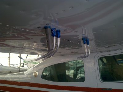
Inlets
The sample air comes into the plane from tubes run to the outside of the plane, either below the wings or right out the side of the aircraft's cabin. This makes sure exhaust from the plane doesn't get into our air sample.
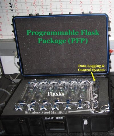
Programmable Flask Package (PFP)
The PFP contains 12 glass flasks for storing the air samples, a flexible stainless steel manifold system connecting the flasks, a data logging system to record the valuable data, and a control system that makes up the brains of the PFP. The 12 cylindrical glass flasks have air-tight glass valves at each end to allow air to flow through, which is motor-controlled by the control system. The flasks are packed in a cushioned container with two rows of 6 stacked on top of each other, as seen in the diagram above. The control system stores programmed information including:
- The Sampling Plan - what altitudes air needs to be sampled,
- The Target Flush Volume - how much air must first flow through the flask before storing the actual air sample that will be analyzed, and
- The Fill Pressure - the pressure at which each flask must be filled up to with the sampled air.
The data logger records the actual flush volumes and fill pressures along with the system's status and a time stamp. The data logger also stores information from external sensors at 10-second intervals including GPS position from the GPS system, air temperature, pressure, and humidity.
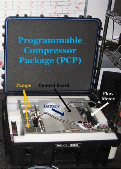
Programmable Compressor Package (PCP)
The PCP contains 2 pumps, a first-stage and second-stage pump that are plumbed in series in order to increase the pumping power, a rechargeable battery, a control board, and a flow meter. The first-stage pump is designed to ensure air will flow at a rate of at least 5 liters per minute at an elevation of 8,000 meters, about 26,000 feet above sea level, which is measured by the flow meter. The second-stage pump is designed to ensure that air samples within flasks can be pumped up to 40 pounds per square inch absolute (psia) at elevations up to 8,000 meters/26,000 feet. Since there is much lower pressure at such high altitudes, the pumps must work harder to push the same amount of air into the flasks. The PCP is powered by a nickel-metal hydride (NiMH) rechargeable battery, which enables the pumps to fill up to 4 PFPs before recharging. The control board makes sure that the whole process of pumping air is running smoothly.
Pilot Display
The pilot display is basically a digital LED screen and toggle switch that communicates sampling altitudes with the pilot from the control system in the PFP. When the pilot reaches one of the pre-determined sampling altitudes, the pilot display will tell the pilot to flip the toggle switch to begin taking the air sample. The pilot display gets this information from the sampling plan programmed in the control system of the PFP.

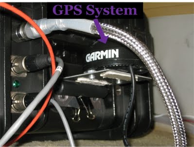
GPS System
The GPS system allows for precise positioning of the aircraft and universal time to be recorded along with the air samples. The position and time is recorded by the data logger within the PFP. The GPS makes tracking the time of the sample much easier by not having to worry about whether the internal clock in the PFP is correct or not, and in the scientific field precision is very important if you want reliable data.
 Previous