Stack Heater Information
The Aerosol system stack heater construction information was updated in February 2009. Below are the construction diagram, materials required list and pictures of the assembly.
PowerPoint Slides of Heater DescriptionMulti page schematic

Part and Tool List
Parts List:
- 1 – 8’ 2” OD stainless steel pipe, chamfered at both ends
- 1 –7’ 4” PVC pipe
- 2 – 4” PVC end caps, with appropriate holes
- 1 – heater (model#=Omegalux fibrox heating cord, HTC-120, 144”, 260 W, 2.17 Amp)
- 1 – shrinkwrap, assorted sizes
- 1 – 70o C thermal cutoff switch (Selco UP62 UCHIYA 70C 066) (rated to 4 Amps for 125Vac) (also used UP72 – slightly different gauge wire)
- 1 – 8’ of 105o C high T wire
- 6 – blue heatshrinkable butt crimps
- 1 – appropriate length of extension cord (105° C)
- 1 – roll of foil tape
- 1 – 1” thick sheet of fiberglass insulation
- N – zip ties (high T)
- 1 – three prong 120 Vac plug or 3 pin connector for back of PID and pins
- 2 – hoseclamps for holding pipe in position
Tools List
- Springloaded crimper
- Wire strippers
- Gloves (for fiberglass)
- Screwdriver(s) for pipe clamps and plug
- Heat gun
- Scissors (for fiberglass and foil tape)
- Crimper for PID connector
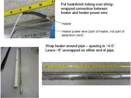
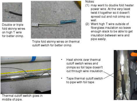
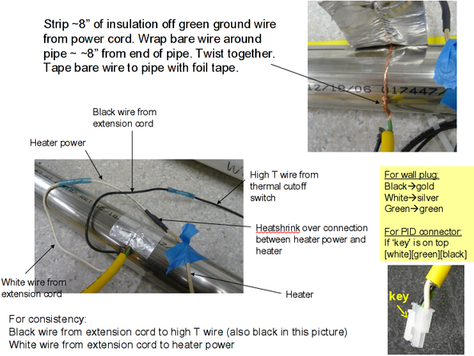
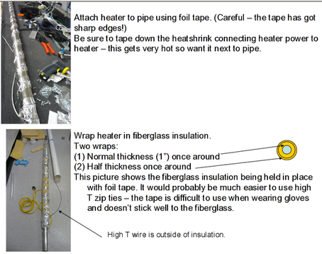
Construction Process