
Instrument Description
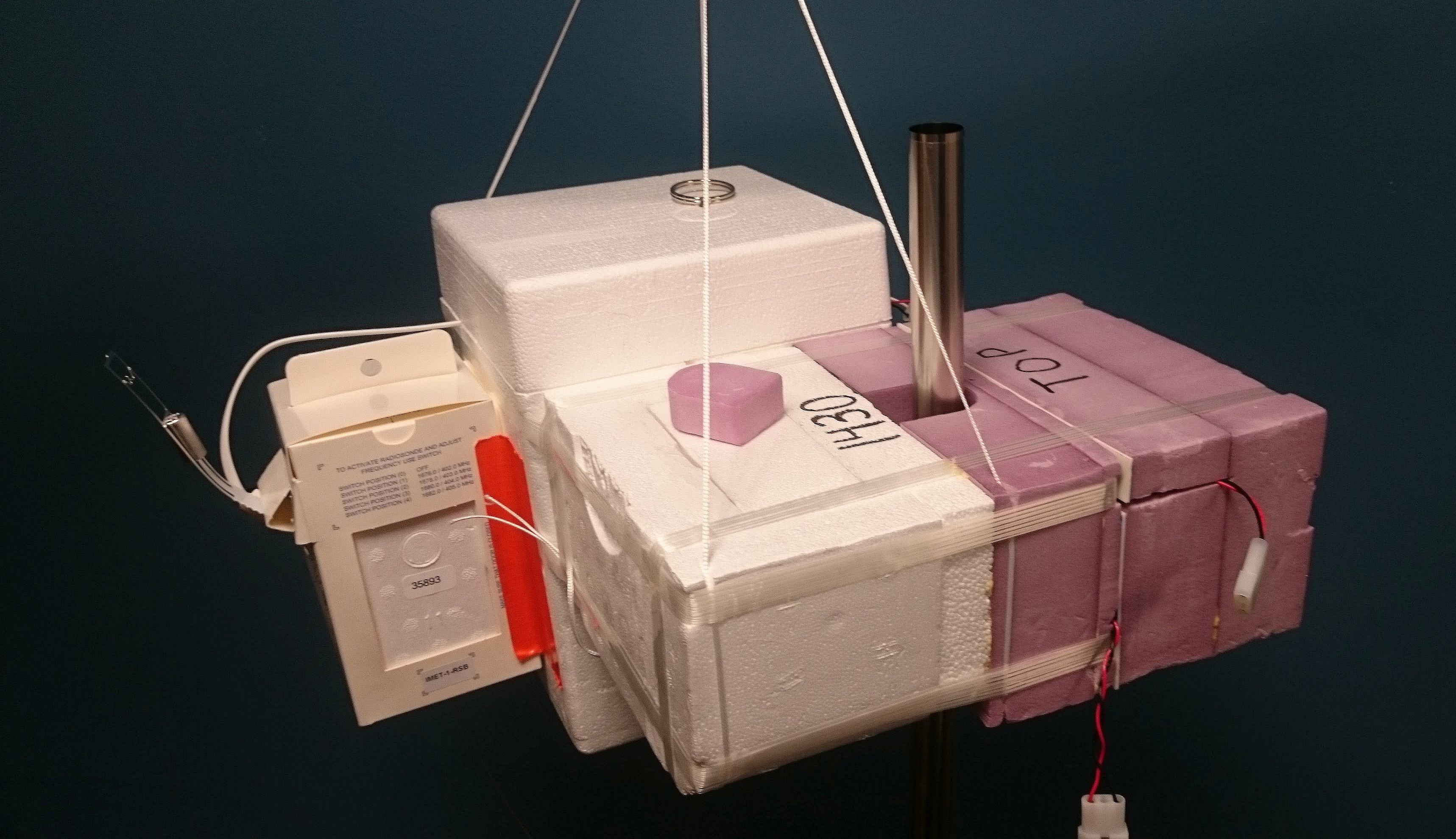
The NOAA FPH and ECC Ozonesonde instrument package.
THE BASIC PRINCIPLE
The maximum amount of vapor-phase water that air can hold before the vapor begins to condense (saturation) is strictly a function of the air temperature. If saturated air is cooled slightly, some of the water vapor turns to to liquid, decreasing the amount of vapor. If saturated air is heated slightly the air will no longer be saturated if there is no additional input of water vapor. Placing a cold object in a stream of saturated air will also condense some of the vapor. If the object is cold enough water vapor in non-saturated air will condense. Depending on the temperature of the cold object the vapor condenses as liquid water (dew) or ice (frost). This is the principle behind dew point and frost point hygrometry.
A great example of this principle is how a cold glass of iced tea “beads up” with water droplets on a hot summer's day. The glass cools the surrounding air and some of the water vapor it holds condenses as liquid water on the glass. The temperature at which water vapor in the air begins to condense as a liquid is called the dew point; this depends on how much water vapor is in the air. Dew points below 0°C (32°F), where water vapor condenses to frost (ice) instead of dew, are known as frost points. This physical principle of the frost point temperature is the basis for our hygrometer that measures the amount of water vapor in air.

TECHNIQUE of FROST POINT HYGROMETRY
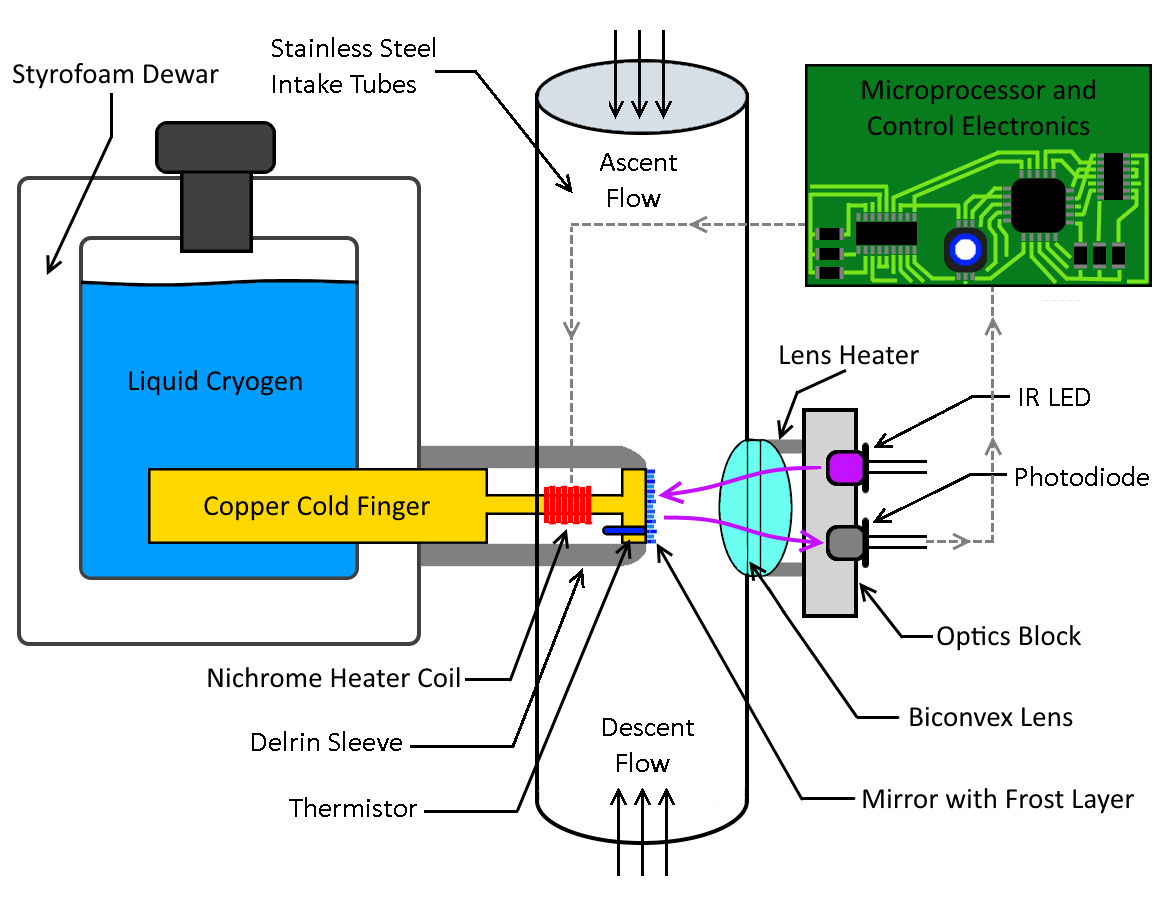
Block Diagram of the NOAA Frost Point Hygrometer (FPH)
The FPH cools a small polished metal mirror situated in a stream of air until a thin layer of dew or frost (condensate) forms on the mirror. Except in in humid environments near the Earth’s surface, this condensate is almost always frost (ice). Once the thin frost layer is deposited on the mirror the FPH applies pulses of heat as needed to stably maintain the frost layer thickness. This intermittent heating competes with continual mirror cooling by a liquid cryogen to produce the desired mirror temperature. As the amount of water vapor in the air stream changes the mirror temperature is adjusted to maintain the frost layer. The thickness of the frost layer is measured by reflecting a small infrared beam (LED) off it to a photodiode (detector). The reflection signal informs the frost control logic whether or not to heat the mirror. Too weak a reflection signal means that the mirror needs heat (frost is too thick) and too strong a signal means that the mirror needs no heat (frost is too thin). The instrument's microprocessor-controlled feedback loop with Proportional-Integral-Derivative (PID) logic will then heat (cool) the mirror surface to reduce (increase) the frost layer to the desired thickness. This feedback occurs many times per second and produces a consistent thickness of frost on the mirror. The controlled frost point temperature of the mirror is a direct measure of how much water vapor is in the air streaming past it.
DATA COLLECTION
Once a balloon is launched there is no physical connection (cable or wire) between the instruments and the ground. Instead, data packets from instruments are transmitted at radio frequencies near 403 MHz by a radiosonde. These telemetered data are received on the ground with an antenna, preamplifier, and high-resolution radio frequency receiver, then are ported to a PC running custom software that records and displays all the parameters measured during a flight. Today’s software (SkySonde) was written specifically for use with International Met Systems (InterMet) iMet-1-RSB radiosondes; our previous software supported Vaisala RS80 radiosondes that are no longer made.
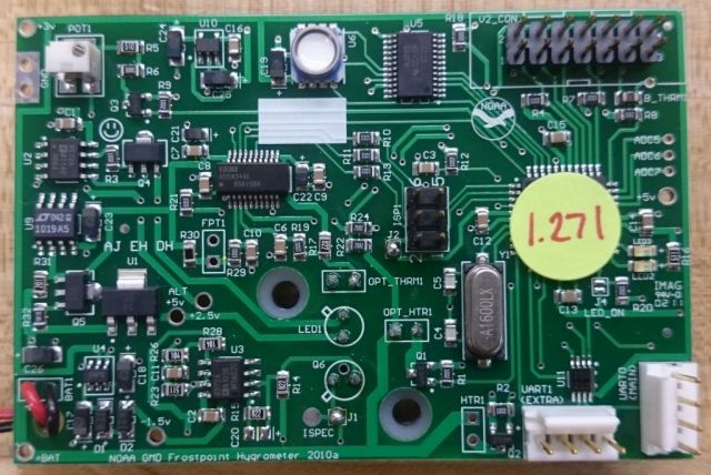
FPH Microprocessor Control Board
VALVED TURNAROUND
Typical balloon soundings use helium to lift the payload at ~5 m/s (11 mph) until the balloon bursts at ~30 km, at which point the payload falls at speeds >30 m/s (>70 mph) despite the efforts of a small parachute. Since our main scientific objective is to obtain high quality water vapor measurements with the FPH during both the ascent and descent phases of each flight, we employ a simple automated valve in the neck of each balloon that releases helium from it to prevent burst. The valve effectively turns the balloon around, from ascending to descending, avoiding the balloon bursting and the payload rocketing down. The valve system includes a miniature pressure sensor that, when reaching a pre-set low-pressure threshold (~16 hPa), sends a signal to open the valve in the neck of the balloon. Once the valve is open the helium slowly releases from the balloon and the payload descends at a controlled rate of ~5 m/s (11 mph). This valve is further described in a publication by Kräuchi et al. [2016].
THE CHASE
In some cases it is desirable to recover the payload after a flight for the purpose of instrument re-use. We utilize Global Positioning System (GPS) data telemetered from the payload to track the balloon using a car-based GPS receiver, laptop computer, and software that displays the current payload location on a road map and provides a rough estimate of where the payload will land. This mobile setup has proven highly effective in recovering payloads, even after they have descended from altitudes >30 km (98,400 ft).