Search
Search GML:
Global Monitoring Laboratory
Earth System Research Laboratories
Menu
Home
About
About GML
Diversity, Equity, and Inclusion
Science Reviews
Safety Program
Employment
Visiting
Contact Us
Intranet
People
Organization
Staff
Staff by Division
Employee Spotlight
Research
Research Overview
Greenhouse Gases
Halocarbons and Trace Gases
Ozone and Water Vapor
Global Radiation, Aerosols and Clouds
Publications
Observing Networks
Overview
Observations Overview
Measurement Sites
Field Campaigns
Atmospheric Baseline Observatories
Observatory Operations
Barrow, Alaska
Mauna Loa, Hawaii
American Samoa
South Pole
Observing Networks
Greenhouse Gas Reference Network
Halocarbons and Trace Gases
Surface Radiation
Federated Aerosol Network
Ozone
Water Vapor
Data
Data
Browse Data Archive
Search for Data
Data by Research Program
Measurement Sites
ObsPack
Tools
Data Viewer
Solar Calculator
Visualization
Data Visualization Pages
South Pole Ozone Hole
Products
Products
Greenhouse Gas Index
Ozone Depletion Index
Trends in CO
2
, CH
4
, N
2
O, SF
6
CarbonTracker
US Potent GHG Tracker
ObsPack
Mauna Loa Apparent Transmission
Barrow Snow Melt Dates
South Pole Ozone Hole
Calibration Facilities
WMO Central Calibration Laboratory
Central UV Calibration Facility
Broadband Solar Calibration Facility
World Dobson Ozone Calibration Centre
Information
News
Seminars
Education/Outreach
Student Opportunities
FAQ's
Publications
Webcams
South Pole Webcam
Mauna Loa Webcams
Barrow Webcam
Global Monitoring Annual Conference
The 52
nd
Conference will be
held May 21 - 22, 2024
Search
Search GML:
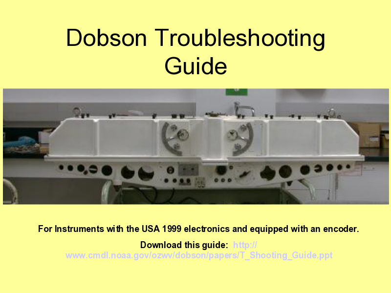
Dobson Troubleshooting Guide
Table of contents
(1) - Dobson Troubleshooting Guide
(2) - Definitions
(3) - Theory of operation
(4) - What can go wrong?
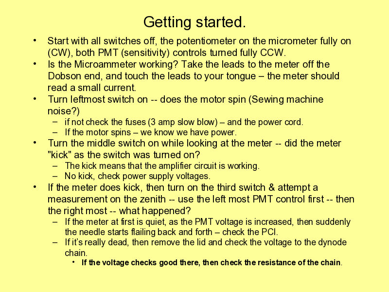
(5) - Getting started.
(6) - Photomultiplier Tube Problems – There aren’t many.
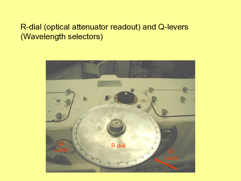
(7) - R-dial (optical attenuator readout) and Q-levers (Wavelength selectors)
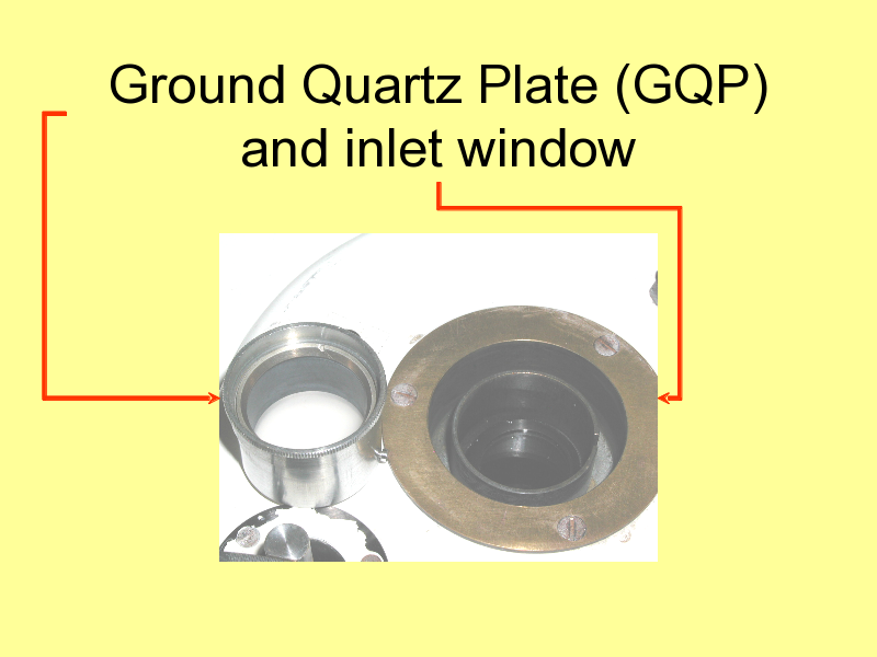
(8) - Ground Quartz Plate (GQP) and inlet window
(9) - Cleaning
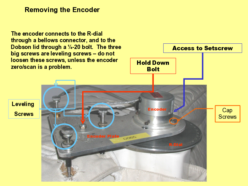
(10) - Removing the Encoder
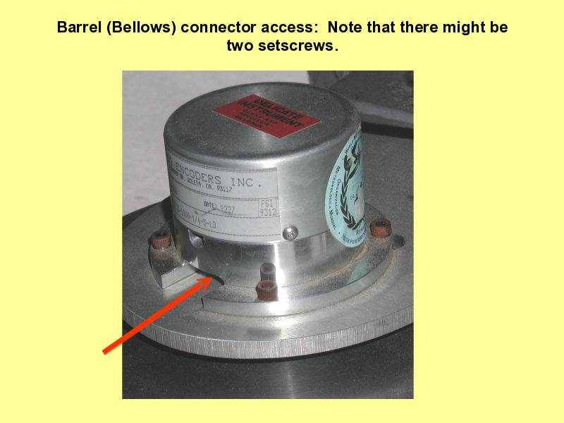
(11) - Barrel (Bellows) connector access: Note that there might be two setscrews.
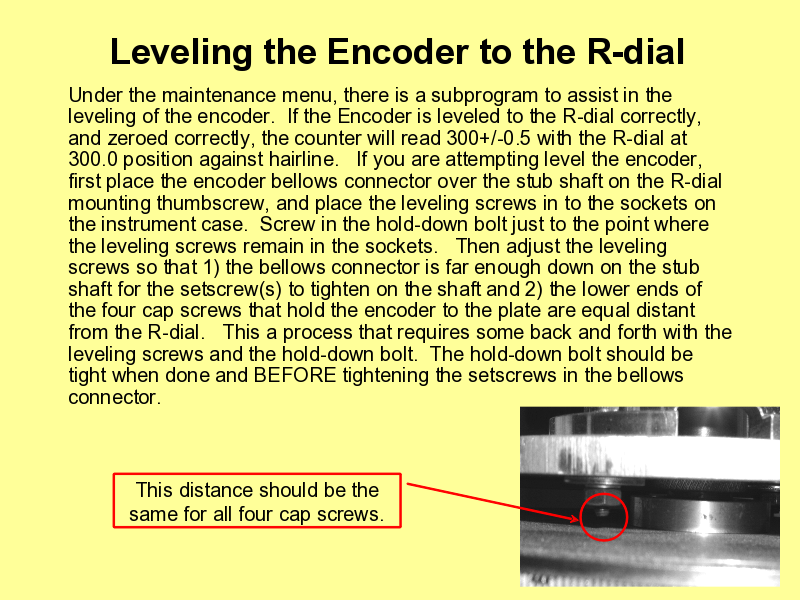
(12) - Leveling the Encoder to the R-dial
(13) - Problems with Encoder/Counter
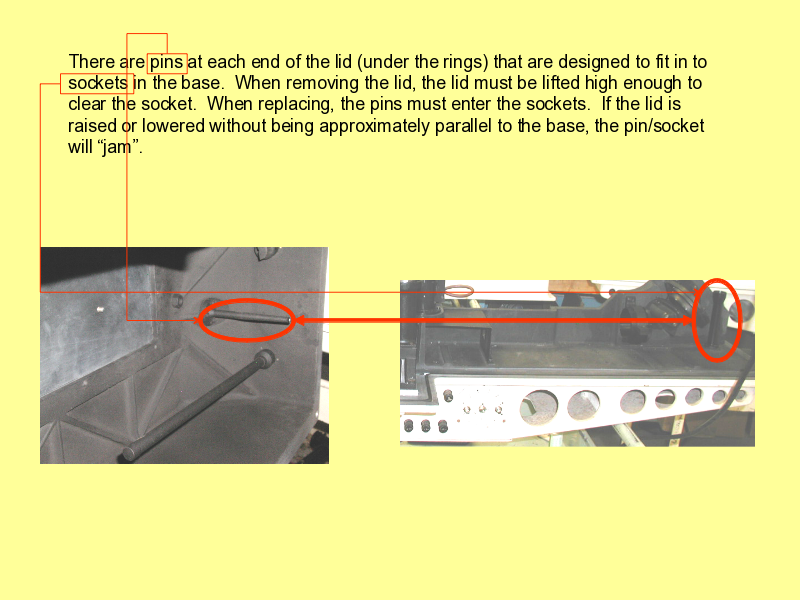
(14) - There are pins at each end of the lid (under the rings)...
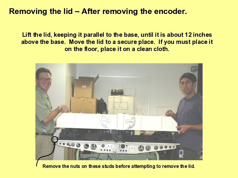
(15) - Removing the lid – After removing the encoder.
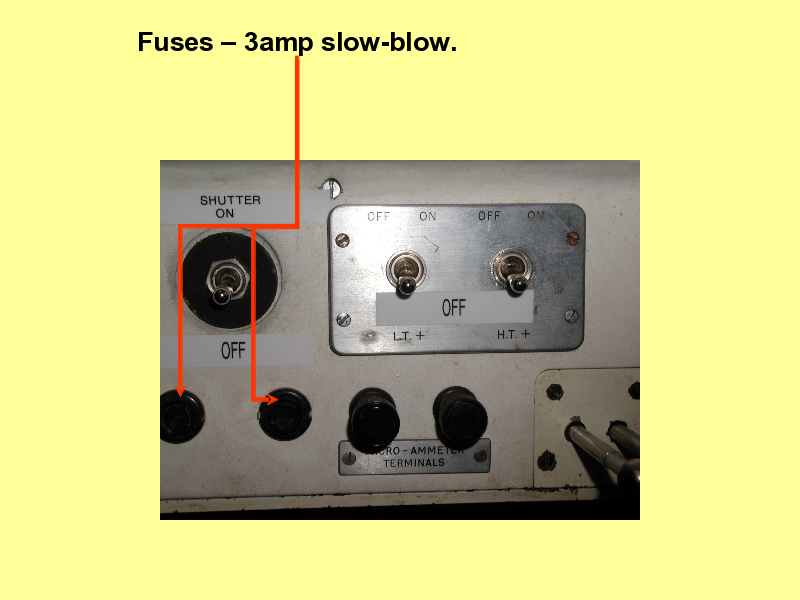
(16) - Fuses – 3amp slow-blow.
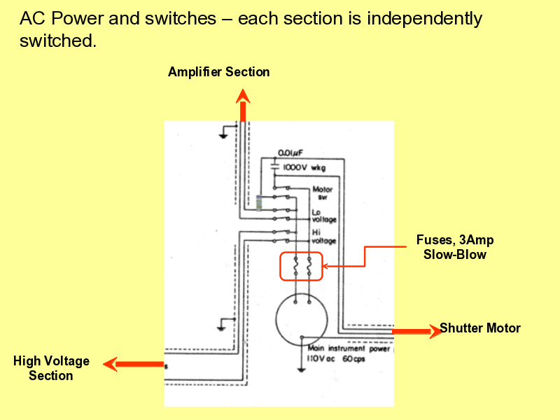
(17) - AC Power and switches – each section is independently switched.
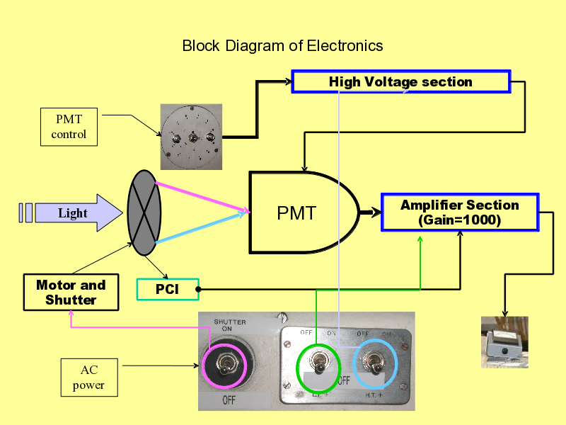
(18) - Block Diagram of Electronics
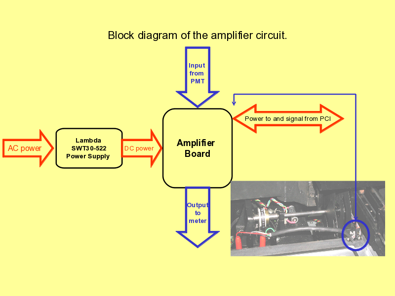
(19) - Block diagram of the amplifier circuit.
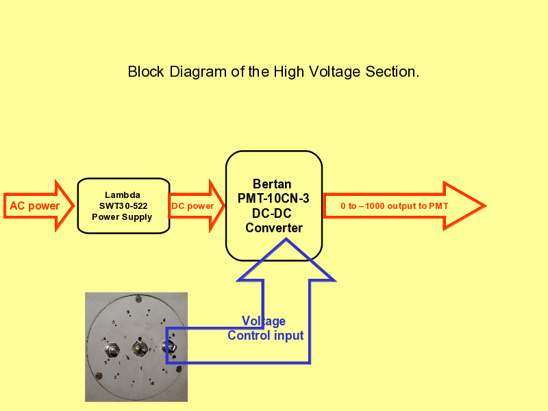
(20) - Block Diagram of the High Voltage Section.
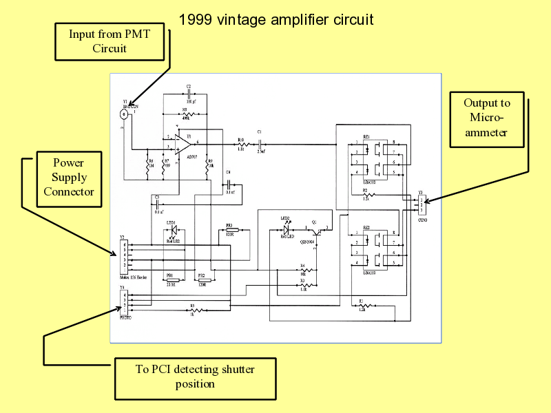
(21) - 1999 vintage amplifier circuit
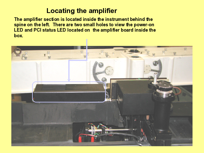
(22) - Locating the amplifier
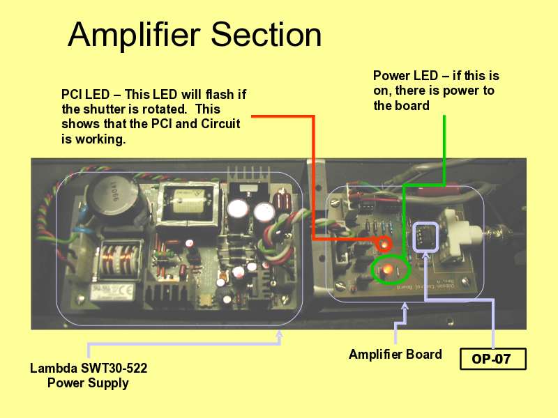
(23) - Amplifier Section
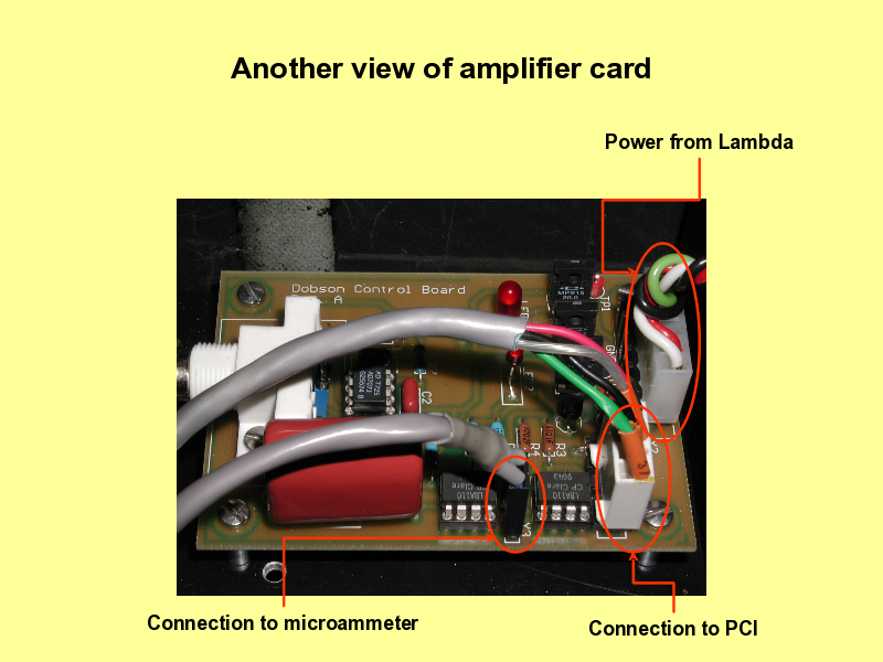
(24) - Another view of amplifier card
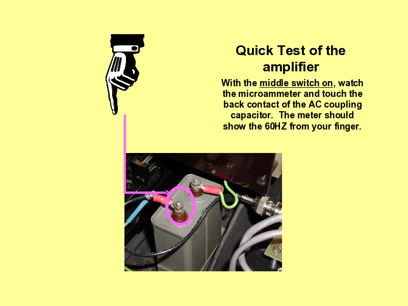
(25) - Quick Test of the amplifier
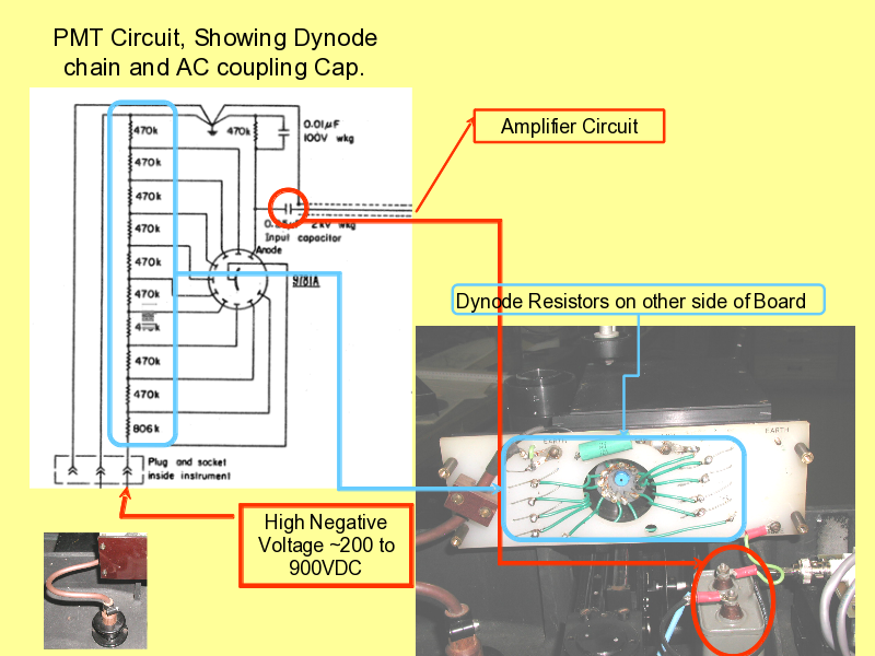
(26) - PMT Circuit, Showing Dynode chain and AC coupling Cap.
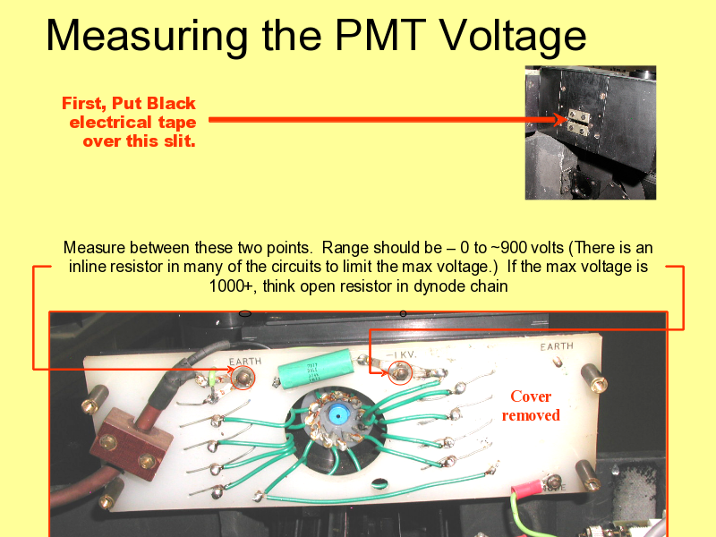
(27) - Measuring the PMT Voltage
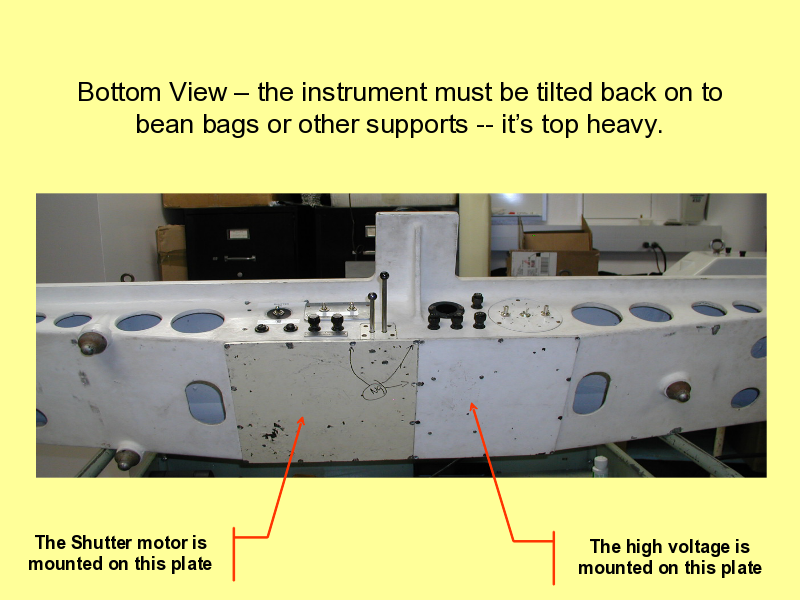
(28) - Bottom View – the instrument must be tilted back on to bean bags or other supports
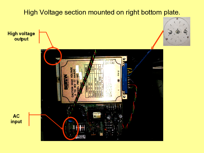
(29) - High Voltage section mounted on right bottom plate.
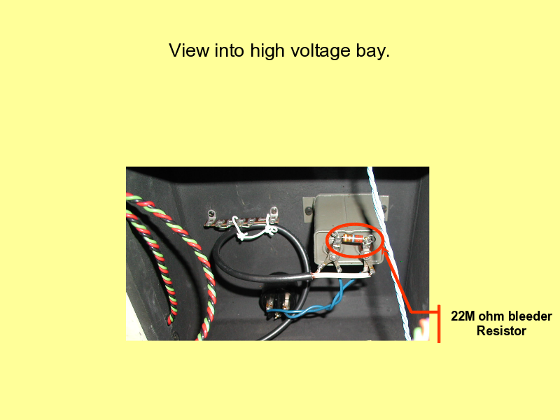
(30) - View into high voltage bay.
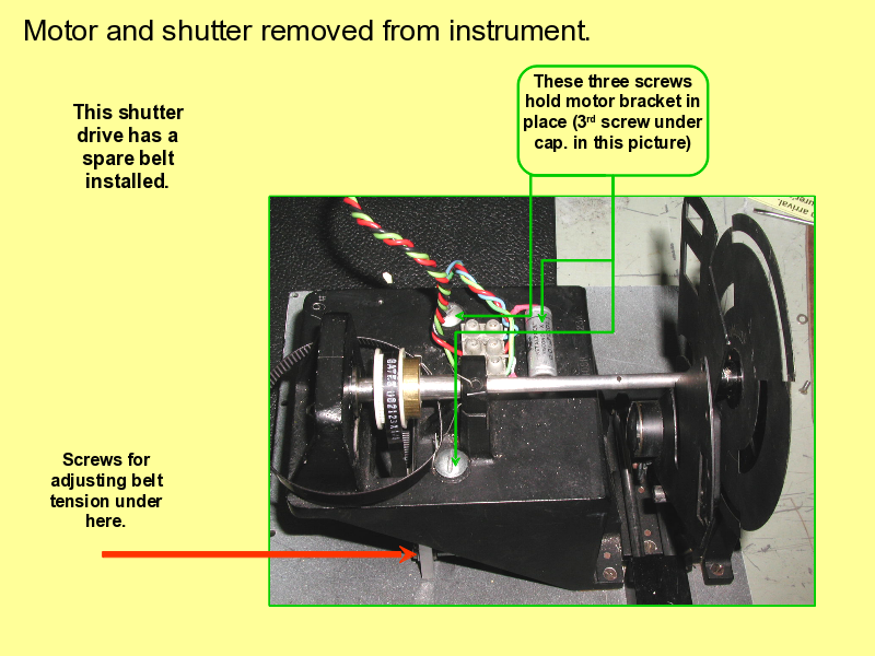
(31) - Motor and shutter removed from instrument.
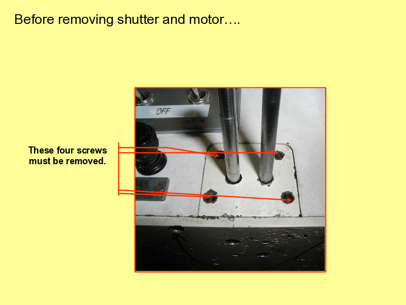
(32) - Before removing shutter and motor….
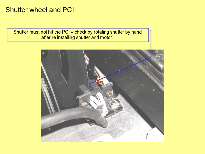
(33) - Shutter wheel and PCI